RedAllison
Well-Known Member
Well I pulled the trigger on the Minn Kota Terrova Ipilot troller. The unique setup on the mount added to the fact that she shaft must slide through the mount makes for unconventional mounting of Side or Down Imaging tranducers. I already had a Hbird 997Si on the bow of my 21 so I certainly wanted to put the transducer on the Terrova. Below are the steps and pics. If you had quickset epoxy and paint I suppose you could do it all in one day but I wanted to assure proper curing so the process took several days. (Pics begin L-R on top row)
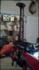
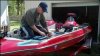
Pic 1: MEGA THANKS to my bud Eric Petty for removing the Maxxum Pro troller I had, drilling and installing the MK quick bracket and then mounting the motor. I just STILL can't bring nor trust myself to drill holes in my baby! :cuss I didn't really want to use the MK plate at first but after reading the owners manual the requirement to have the motors shaft at least 1.5" away from the rubrail necessitated the use of the plate. (Honestly it wouldn't take a couple of minutes to remove the transducer cable from under the bow if I wanted to remove the troller but that'll never happen, I didn't buy the 21 for lightweight, flatout speed) Eric operates Bassboat Outfitters in Henderson, TN and if you've been to the last couple of Fastpass Rallies you've seen Eric in his white/purple single console Stroker. Checkout his Bassboat Outfitters page on Facebook!
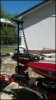
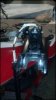
Pic 2: The mounted motor, ready to be carried home and the Si transducer operation began.
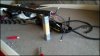
Pic 3: ("Custom" motor support optional. :big grin ) Since the shaft must be slid through the motors base, the head of the motor must first be removed. That only necessitated the removal of 5 bolts, 4 that hold the plastic top on the head itself and 1 thru the shaft that attaches it all onto the shaft. This motor has the "Universal Transducer" built into it so that cable was disconnected and I did away with that end of the cable that ran out of the head, down through the spiraled main power chord where it would then attach to a standard 2D flasher. The remaining 3 wires are the +/- power chords and the thin brown wire with a fuse link in it. DON'T discard or cut those blue sheaths that come wrapped around the power cables, they AREN'T fancy heatshrink... they are weaved looms that cutdown on radio/noise interference to any depthfinders! With all that removed, you simply slide the shaft out of the mount and prepare it for the next step.
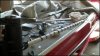
Pic 4: The shaft on this motor has a preformed groove in it that is a good place to mount the transducer cable for the Hbird Si unit into. (Sorry Lowrance users, I understand that Lowrance Si transducer cable is to big in diameter for this epoxy trick. I'm "sure" Johnson Outdoors owning both Hbird & MinnKota DIDN'T plan that! :razz ) The transducer is mounted on a Transducer Shield mount. I wrapped the exposed cable on the lowerunit in plastic tubing/cable sheating for extra insurance when I first mounted the 997 up front a few years back, works perfectly. 3 zipties snug the cable up as it goes from the top of the lowerunit to the bottom of the shaft. Make sure you position the cable to be inline with the center of the shaft groove! I then used a 2 part marine epoxy and "glued the cable" to the shaft in 2"-3" sections, "painting" the epoxy onto the shaft with a small paintbrush. To keep tension on the cable for proper epoxy curing I used alternating strips of masking tape and zipties. If you wrapped the whole thing in tape I assume improper airflow would inhibit proper curing? That was my partial reason for the zipties... the other reason for the zipties was to still hold the cable after I removed the tape after a day of curing. Once the tape was removed I used another small paintbrush to epoxy both sides of the cable so that effectively 3 sides of the cable is bonded into the shaft groove. Once again I let that cure for another day before removing the zipties. (obviously you don't want to remove the ties on the very top and bottom of the shaft!)
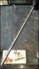
Pic 5: The finished epoxy job. Not pretty but this shows you what it all looked like before paint. I'm pretty confident in the strength and I paid extra attention when applying the epoxy everywhere to cover/prevent any holes/gaps in the epoxy for water to possible freeze and cause problems in.
Pic 6: Now ready for paint, I taped off and masked everything but the groove/cable itself. For paint I used Krylon's "Fusion" in satin black. That paint is supposed to be especially made for plastics and semi-flexible surfaces. I put 3 coats on, allowing appx 6hrs cure time between coats.
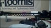
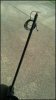
Pic 7: The paint complete and masking removed. Now ready for re-installation.
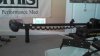
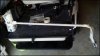
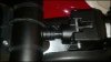
Pic 8: This is the bottom of the motor mount that the shaft will be reinstalled through. Taping power wires onto the transducer cable made it much easier to install the shaft through the mount as it's a snug fit.
Pic 9: This pic shows the 3 zipties at the bottom of the shaft.
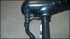
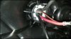
Pic 10: I reinstalled the bolt in the shaft that holds the head assembly atop the shaft. I did this as a reminder to make sure you watch this when you are reinstalling that bolt through the bottom of the head assembly and shaft so that you DON'T screw the bolt through one of the wires! :help KEEP THIS IN MIND...
Pic 1: MEGA THANKS to my bud Eric Petty for removing the Maxxum Pro troller I had, drilling and installing the MK quick bracket and then mounting the motor. I just STILL can't bring nor trust myself to drill holes in my baby! :cuss I didn't really want to use the MK plate at first but after reading the owners manual the requirement to have the motors shaft at least 1.5" away from the rubrail necessitated the use of the plate. (Honestly it wouldn't take a couple of minutes to remove the transducer cable from under the bow if I wanted to remove the troller but that'll never happen, I didn't buy the 21 for lightweight, flatout speed) Eric operates Bassboat Outfitters in Henderson, TN and if you've been to the last couple of Fastpass Rallies you've seen Eric in his white/purple single console Stroker. Checkout his Bassboat Outfitters page on Facebook!
Pic 2: The mounted motor, ready to be carried home and the Si transducer operation began.
Pic 3: ("Custom" motor support optional. :big grin ) Since the shaft must be slid through the motors base, the head of the motor must first be removed. That only necessitated the removal of 5 bolts, 4 that hold the plastic top on the head itself and 1 thru the shaft that attaches it all onto the shaft. This motor has the "Universal Transducer" built into it so that cable was disconnected and I did away with that end of the cable that ran out of the head, down through the spiraled main power chord where it would then attach to a standard 2D flasher. The remaining 3 wires are the +/- power chords and the thin brown wire with a fuse link in it. DON'T discard or cut those blue sheaths that come wrapped around the power cables, they AREN'T fancy heatshrink... they are weaved looms that cutdown on radio/noise interference to any depthfinders! With all that removed, you simply slide the shaft out of the mount and prepare it for the next step.
Pic 4: The shaft on this motor has a preformed groove in it that is a good place to mount the transducer cable for the Hbird Si unit into. (Sorry Lowrance users, I understand that Lowrance Si transducer cable is to big in diameter for this epoxy trick. I'm "sure" Johnson Outdoors owning both Hbird & MinnKota DIDN'T plan that! :razz ) The transducer is mounted on a Transducer Shield mount. I wrapped the exposed cable on the lowerunit in plastic tubing/cable sheating for extra insurance when I first mounted the 997 up front a few years back, works perfectly. 3 zipties snug the cable up as it goes from the top of the lowerunit to the bottom of the shaft. Make sure you position the cable to be inline with the center of the shaft groove! I then used a 2 part marine epoxy and "glued the cable" to the shaft in 2"-3" sections, "painting" the epoxy onto the shaft with a small paintbrush. To keep tension on the cable for proper epoxy curing I used alternating strips of masking tape and zipties. If you wrapped the whole thing in tape I assume improper airflow would inhibit proper curing? That was my partial reason for the zipties... the other reason for the zipties was to still hold the cable after I removed the tape after a day of curing. Once the tape was removed I used another small paintbrush to epoxy both sides of the cable so that effectively 3 sides of the cable is bonded into the shaft groove. Once again I let that cure for another day before removing the zipties. (obviously you don't want to remove the ties on the very top and bottom of the shaft!)
Pic 5: The finished epoxy job. Not pretty but this shows you what it all looked like before paint. I'm pretty confident in the strength and I paid extra attention when applying the epoxy everywhere to cover/prevent any holes/gaps in the epoxy for water to possible freeze and cause problems in.
Pic 6: Now ready for paint, I taped off and masked everything but the groove/cable itself. For paint I used Krylon's "Fusion" in satin black. That paint is supposed to be especially made for plastics and semi-flexible surfaces. I put 3 coats on, allowing appx 6hrs cure time between coats.
Pic 7: The paint complete and masking removed. Now ready for re-installation.
Pic 8: This is the bottom of the motor mount that the shaft will be reinstalled through. Taping power wires onto the transducer cable made it much easier to install the shaft through the mount as it's a snug fit.
Pic 9: This pic shows the 3 zipties at the bottom of the shaft.
Pic 10: I reinstalled the bolt in the shaft that holds the head assembly atop the shaft. I did this as a reminder to make sure you watch this when you are reinstalling that bolt through the bottom of the head assembly and shaft so that you DON'T screw the bolt through one of the wires! :help KEEP THIS IN MIND...
Attachments
-
 20.8 KB Views: 94
 -
 10.1 KB Views: 90
 -
 19.8 KB Views: 83
 -
 21.3 KB Views: 82
 -
 9.6 KB Views: 79
 -
 19.8 KB Views: 76
 -
 9.8 KB Views: 70
 -
 8.6 KB Views: 71
 -
 15.4 KB Views: 71
 -
 17.8 KB Views: 71